
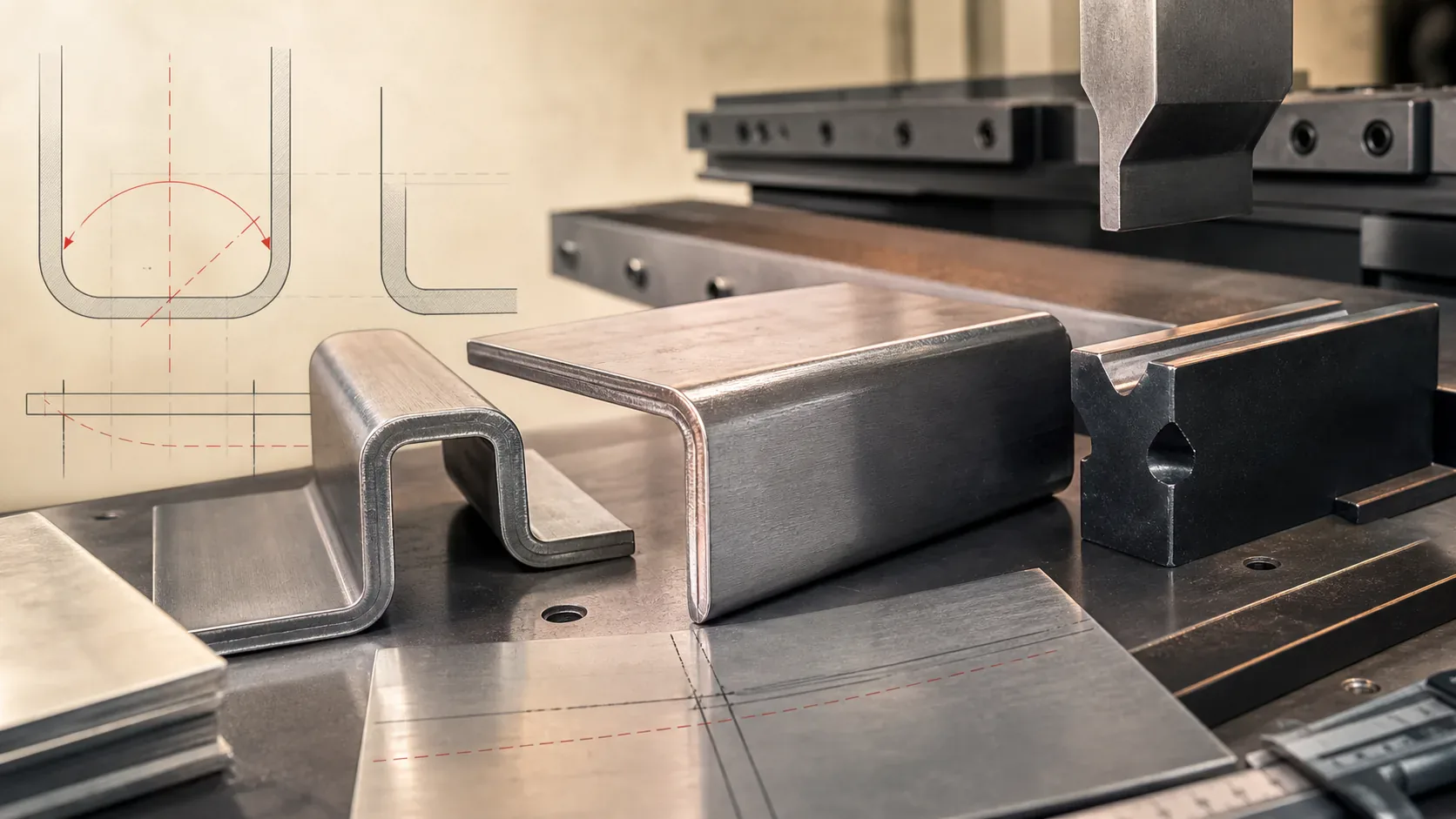
What is bend radius and why does it matter?
Bend radius is the inside radius of a folded sheet — measured from the inside corner of the bend. Too small a radius cracks brittle materials (aluminum, hardened steel) and stretches mild steel beyond its yield point. Too large a radius weakens the structural integrity of the bend.
The minimum bend radius is material- and thickness-dependent. As a starting point: mild steel can handle a radius equal to the material thickness (1× T). Aluminum 6061-T6 needs at least 1.5× T to avoid cracking on the outer fibre. Stainless 304/316 falls between, around 1.25× T for clean bends.
Radius is below half the material thickness. Outer fibre stretches past its elongation limit, work-hardens, then cracks — common on 304 stainless and 6061-T6 aluminum at tight bends.
Radius equals material thickness — the conservative starting rule for mild steel. Inside surface compresses, outside stretches within the elongation limit, no cracking. Quote runs through normally.
What's the default bend radius if I don't specify one?
On our Amada HDS 1303 NT press brake, we default to a radius matched to the punch tooling we have set up — typically 0.080″ to 0.250″ depending on the material gauge and the punch in the program. If you don't specify, we use whatever produces a clean bend without cracking, which is almost always 1× T to 1.5× T.
If your design depends on a specific bend radius (mating part, gasket seat, weld prep) — call it out on the drawing. We'll match it or explain the tooling change required.
How tight a bend angle tolerance can you hold?
±0.5° on bend angle, verified at first article. Repeat parts in the same run hold within ±0.25° once the program is dialed in. The Amada's CNC backgauge positions to ±0.002″, so dimensional tolerance on the bend location is much tighter than the angle tolerance.
For parts that need ±0.25° or tighter (precision optical mounts, mating fixtures), we'll quote first-article inspection on every part rather than batch-sample. Springback compensation is built into every program — your bend comes off at the spec angle, not 2° flatter.
What are the common mistakes to avoid?
- Specifying a bend radius smaller than the material can support → cracks, especially on aluminum and stainless
- Drawing bends that interfere with adjacent features (holes, edges) — the bend deforms the metal in a 3-4× T zone around the bend line
- Assuming the K-factor (the neutral axis position) is universal — different materials and thicknesses use different K-factors, which affects flat-pattern dimensions
- Forgetting that bend allowance changes with material thickness — a 16 GA part and a 1/4″ part with the same outside dimensions need different flat patterns
We handle all of this on our end — your CAD file goes through bend-allowance compensation before the press brake program is generated. Free DFM review on every quote catches the issues before they cost a re-bend.
Bend radius cheat sheet by material
- Mild Steel (A36, hot-rolled): 1× T minimum, 1.5× T preferred for production
- Mild Steel (cold-rolled): 1× T minimum, 1.5× T for tight aesthetic work
- Stainless 304: 1.25× T minimum, 2× T for visible-finish work
- Stainless 316: 1.5× T minimum (more brittle than 304)
- Aluminum 6061-T6: 1.5× T minimum, 2× T for production reliability
- Aluminum 5052: 1× T minimum (more formable than 6061)
- Galvanized Steel: 1× T minimum, but watch for zinc-coating cracks at the bend — call out the finish requirement
Send us the drawing — we'll match the radius to your tooling spec and material grade.
| Material | Practical start | Watch for |
|---|---|---|
| Mild steel | 1x T | Paint or powder coat may change finish requirements. |
| 304 stainless | 1.25x T to 2x T | Visible grain and work hardening around tight bends. |
| 316 stainless | 1.5x T to 2x T | Higher cost and more conservative forming review. |
| 6061-T6 aluminum | 1.5x T to 2x T | Cracking risk when the radius is too tight. |
| 5052 aluminum | 1x T to 1.5x T | More formable than 6061, but still needs bend direction review. |