
SMS Laser & Fabrication
Guide8 min read

Laser Cutting Design Rules for Sheet Metal Parts

If you're designing a part for laser cutting, a few practical rules decide whether your CAD file becomes a clean part, a DFM question, or a re-cut. Here's what an ISO 9001:2015 Brampton fabricator checks before the laser fires.

Laser CuttingDFMKerfSheet MetalCAD Files

SMS Laser & Fabrication

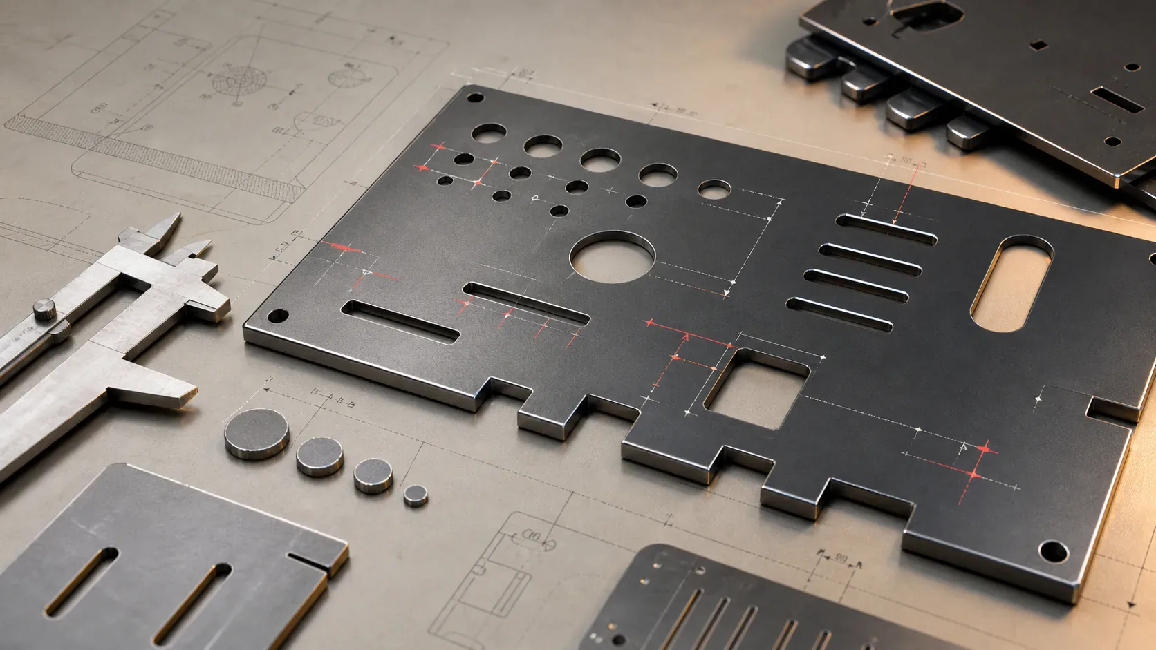
Technical editorial image of laser cut sheet metal parts with holes, slots, tabs, and CAD-style layout marks
Laser-cut feature design is easier to quote when hole size, edge clearance, kerf, and file intent are clear before programming.
Quick Take

The decision points buyers should check first.

  • Use hole diameters at least equal to material thickness unless the part is being reviewed for a secondary operation.
  • Keep slots, holes, and fine features at least one material thickness away from an outside edge when possible.
  • Draw the part to nominal dimensions; let the CAM programmer handle kerf compensation unless a special fit is required.
  • Send DXF, DWG, STEP, IGES, or a dimensioned PDF with material, thickness, quantity, finish, and critical tolerances.
LASER + ASSIST GASTHAZ — heat-affected zonetempered ~ 0.005-0.020 inKerf width~0.005-0.015 in (material + power)Dross zonere-solidified ejecta — usually skips deburrTop edge (clean)first surface — best squareCross-section view ⎯ material in section, laser cutting top→bottom
The cross-section every design rule in this guide refers back to. Holes, slots, and edge features all interact with the kerf width and HAZ — that’s why “hole ≥ T” and “edge ≥ T” are the starting design rules.
Anatomy of a laser-cut edge — kerf, heat-affected zone, striations, and the dross zone at the bottom of the cut. Every design rule in this guide starts here.
Buyer Checklist

What to confirm before sending a quote.

  • Best file

    DXF or DWG for flat profiles; STEP or IGES when bends, machined features, or assemblies affect the quote.

  • Critical callouts

    Material grade, sheet thickness, quantity, finish, visible faces, and any tolerance tighter than +/-0.010 in.

  • Production clue

    Tell us whether this is a one-off, prototype, pilot run, or repeat production release so we quote the right process path.

01Chapter

What's the minimum hole size for laser cutting?

The general rule: hole diameter should be at least equal to the material thickness. A 1/4″ hole in 1/4″ mild steel is feasible. A 1/8″ hole in 1/4″ steel is risky — the kerf width and heat input start fighting the geometry, and the slug can stick or the hole can come out tapered.

For production-grade quality on holes smaller than the material thickness, expect either a slightly larger drilled hole as a secondary operation, or a tighter tolerance review at quote time. We flag it on every DFM review rather than discovering the issue at the first article.

Too tight — needs DFM review
1/8″ hole in 1/4″ steelHOLE < T

Hole diameter is smaller than the material thickness. Risks include tapered hole walls, slug sticking, and inconsistent circularity. We flag it on DFM and recommend a drilled secondary or a tighter quote review.

Clean fit — quote as drawn
1/4″ hole in 1/4″ steelHOLE = T

Hole diameter equals material thickness — the conservative starting rule. Edge quality is consistent, slug ejects cleanly, and the part runs through production with no extra setup.

Two parts, same 1/4″ mild steel, different hole diameters. The rule that matters: hole ≥ material thickness. If the design needs a smaller feature, send it as a drawing note and quote it with a secondary operation.
02Chapter

How close to the edge can a feature be?

Keep features at least 1× the material thickness away from any edge. A hole edge or slot edge sitting closer than that risks blowing through the material between the feature and the edge — leaves you with a slot instead of a hole, or a torn edge.

For parts that have to push that limit (compact brackets, electrical chassis with crowded layouts), we'll quote it but flag the risk. Sometimes a 0.5× thickness edge clearance works in 16 GA, but it never works in 1/4″ plate.

hole >= Tedge >= TT
Design Rule

Use material thickness as the starting unit. If a hole, slot, or edge clearance is smaller than T, it needs a DFM review before production.

03Chapter

What is kerf compensation and do I need to worry about it?

Kerf is the width of material the laser actually removes — typically 0.005″ to 0.015″ depending on power, gas, and material thickness. If your part has a hole drawn at exactly 0.250″, the cut hole will be slightly larger than that because the laser cuts on either side of the line.

Most CAM software (and our shop's programmers) compensate for this automatically — the tool path offsets inward on holes and outward on perimeters by half the kerf. You don't need to compensate in your CAD file. Just draw to the nominal dimension. Tell us if you need a tighter-than-±0.005″ tolerance and we'll either route the part to a secondary operation or use a tighter program.

black dashed: nominal CAD geometryred: CAM offsets by half the kerf
Draw the profile to the finished dimension. The programmer offsets the tool path for inside and outside cuts so the final part lands on nominal size.
04Chapter

Do I need to add tabs to keep parts from falling through?

Usually not. Modern fiber and CO₂ lasers (including our TRUMPF Trumatic L3050) hold parts in place with the assist gas pressure plus the ribbed bed of the cutting table. Most parts up to 16″ × 16″ stay put without tabs.

Small parts (under 2″ in any dimension) on thin material may need micro-tabs — small uncut sections that connect the part to the parent sheet. We add these automatically when needed and break the tab off cleanly during deburring. You don't need to design them in.

05Chapter

What file formats give the cleanest quote?

DXF and DWG are the fastest path to quoting. STEP and IGES files for 3D geometry get unfolded to flat patterns at our end. PDF works but adds an hour of re-tracing — we charge for the time only when the file is genuinely problematic.

The must-have details: dimensions, material, thickness, quantity, and any tolerance tighter than ±0.010″ called out specifically. Bonus points for noting the application — if we know it's an outdoor part, we'll suggest galvanized; if it's food-grade, 304/316 stainless. Free DFM review on every quote.

01
DXF / DWG
Flat profiles — fastest quote turnaround
02
STEP
3D model with bend intent + machined features
03
IGES
Older 3D format — works, slower import
04
PDF (dimensioned)
Acceptable for simple geometry + tolerance callouts
05
Photo / sketch
Manual re-draw — flag turnaround impact at quote
File quality directly affects quote speed. Sending the right file for the part type usually saves a day of back-and-forth.
References

Sources behind the guide.

  1. 01TRUMPF
    Laser cutting process overview
  2. 02ISO
    ISO 9013 thermal cut classification
Common Questions

Questions buyers ask.

  • Can I send a paper sketch instead of CAD?

    Yes — paper sketches with critical dimensions noted work fine for quoting. We can re-create the geometry in CAD on our end. Send a clear photo with dimensions in inches or millimetres. If any dimension is critical, mark it; everything else we'll cut to nominal.

  • What's the maximum thickness you can laser cut?

    Mild steel up to 1.00", stainless steel up to .75", aluminum up to .5" on our TRUMPF Trumatic L3050. Galvanized and pre-painted stock cut to .25" without finish damage. For thicker plate we route to plasma cutting through a partner shop — we'll tell you up front if your job needs that.

  • How tight a tolerance can I expect?

    ±0.005" repeatable on our laser, verified at first article. Most production work runs ±0.010" to ±0.015" depending on material thickness and part complexity. For tighter-than-±0.005" tolerances we route the part to the press brake or mill for secondary finishing — included in the quote.

  • Is there a cost for design feedback?

    No — DFM (design for manufacturability) review is free on every quote. We flag features that won't cut cleanly, suggest alternatives, and explain cost trade-offs. Fixing it on the screen costs nothing; fixing it at the laser costs a re-cut.

Send us a drawing.

DXF, DWG, STEP, IGES, PDF, or a hand sketch — we’ll quote it the same day, with parts on your dock within the week.